555 Timer Schematic Diagram / 30 Minute Timer Circuit Using 555 Ic And 7555 Ic : This integrated circuit can be used in a variety of ways from which the basic one is to produce accurate and stable delays in electronic circuits.additionally, it is available in 8 pin dip and 14 pin dip.
555 Timer Schematic Diagram / 30 Minute Timer Circuit Using 555 Ic And 7555 Ic : This integrated circuit can be used in a variety of ways from which the basic one is to produce accurate and stable delays in electronic circuits.additionally, it is available in 8 pin dip and 14 pin dip.. An external triggering is required for transition from stable to unstable state. Look at the block diagram again. There is also a 556 dual version of 555 timer which consists of two complete 555 timers in 14 dip and a 558 quadruple timer which is consisting of four 555 timer in one ic and is available as a 16 pin dip in the market. The working modes of a 555 timer are astable, bistable, and monostable. We connect a 100μf capacitor to the positive voltage supply and then to pin 2.
Additional • timing from microseconds through hours terminals are provided for triggering or resetting if • operates in both astable and monostable modes desired. 500ms is the same as saying 0.5s so by rearranging the formula above, we get the calculated value for the resistor, r as: The 555 timer is a simple integrated circuit that can be used to make many different electronic circuits. Fig 1 shows the pin connections to the 555 timer, it was take directly from the 555 timer datasheet. 555 timer, as the name specified, are the electronics circuits used for measuring time intervals.in this article, we will cover about 555 timers.
1 from It is connected to ground as usual. 555 timer circuit | circuit diagram. The reset input current draw illustrates the need for a current limiting resistor as shown in some of the preceding circuits. There is also a 556 dual version of 555 timer which consists of two complete 555 timers in 14 dip and a 558 quadruple timer which is consisting of four 555 timer in one ic and is available as a 16 pin dip in the market. Compare pricing, distributors & save. The 555 ic timer circuit above shows a very straightforward design where the ic 555 forms the central controlling part of the circuit. 555 one shot timer | circuit diagram. For 5 min, 10 min and 15 min you just have to change the resistor value (r 1).
Now as shown in figure, there are eight pins for a 555 timer ic namely, 1.ground.
The 555 timer is a simple integrated circuit that can be used to make many different electronic circuits. With this information you will learn how how the 555 works and will have the experience to build some of the circuits below. Basic 555 monostable multivibrator circuit. Because of their availability and ease of use, the 555 astable circuit is the common source of clock signal in many synchronous circuits. This pin has no special function what so ever. The power connections to the chip are through pins 1 (ground) and 8 (+vcc). 555 timer, as the name specified, are the electronics circuits used for measuring time intervals.in this article, we will cover about 555 timers. A collection of 555 circuits using the 555 timer as an astable oscillator with different duty cycles. The breadboard schematic of the above circuit is shown below. Compare pricing, distributors & save. 8.power or vcc pin 1. Here is a 555 timer circuit project. There is a huge list of 555 ic circuits due to which this ic is very popular among electronics hobbiests, students and experimenters.
This pin has no special function what so ever. The reset input current draw illustrates the need for a current limiting resistor as shown in some of the preceding circuits. There is also a 556 dual version of 555 timer which consists of two complete 555 timers in 14 dip and a 558 quadruple timer which is consisting of four 555 timer in one ic and is available as a 16 pin dip in the market. The next diagram shows the basic current consumption of 555 timer chips from different manufacturers. Lm555 timer 1 features 3 description the lm555 is a highly stable device for generating 1• direct replacement for se555/ne555 accurate time delays or oscillation.
555 Timer from www.tutorialspoint.com Compare pricing, distributors & save. It is easy with a relay directly. This circuit uses very basic components like 555 timer and 4017 counter. The reset input current draw illustrates the need for a current limiting resistor as shown in some of the preceding circuits. Pin 2 detects a voltage below 1/3 of the supply voltage to turn the ic on. The next diagram shows the basic current consumption of 555 timer chips from different manufacturers. In the place of the push switch s1 / trigger switch you can also connect the output of any project to trigger the timer. Referring to the timing diagram in figure 3, a low voltage pulse applied to the trigger input (pin 2) causes the output voltage at pin 3 to go from low to high.
Find every electronic parts on octopart.
It is connected to ground as usual. In short, the 555 timer chip works by detecting threshold voltage levels. And, pin 6 detects a voltage above 2/3 of the supply voltage to turn the ic off. It is easy to make and portable with small pcbs. 555 timer pin diagram and descriptions. For 5 min, 10 min and 15 min you just have to change the resistor value (r 1). The 555 timer is a simple integrated circuit that can be used to make many different electronic circuits. You can use it for the snooze alarm with a buzzer. Simple 555 timer circuits & projects. Adjustable on off timer(using 555 astable mode) in this circuit a timer with cyclic on off operations is designed. Here is a 555 timer circuit project. We connect a 100μf capacitor to the positive voltage supply and then to pin 2. The figure below shows a very useful project of a 555 adjustable repeat timer circuit.
555 ic automatically switches back to. Monostable multivibrator (mmv) mode of 555 timer ic is also called single shot mode. This is a 555 one shot timer circuit. And, pin 6 detects a voltage above 2/3 of the supply voltage to turn the ic off. The positive supply voltage (+vcc) should be between 5 and 15v.
Amazing Animation Of Astable Mode Operation Of 555 Timer With Circuit Diagram Funny Electronics from 3.bp.blogspot.com In the place of the push switch s1 / trigger switch you can also connect the output of any project to trigger the timer. An external triggering is required for transition from stable to unstable state. The breadboard schematic of the above circuit is shown below. 555 timer helpers schematic the addition of a capacitor to the trigger will not work for short output pulses as there is also a short delay in the recovery of the trigger terminal voltage. Figure 2 shows the basic 555 timer monostable circuit. Here is a 555 timer circuit project. The second 555 timer helper will extend the timers output duration without having to use large values of r1 and/or c1. These on off intervals can be adjusted by varying the 555 timer output and number of counter outputs.
Each mode of operation indicates a circuit diagram and its output.
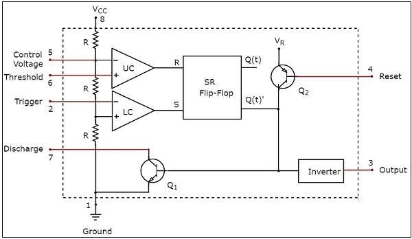
555 timer was first introduced by signetics corporation in 1971 as se555/ne555. Look at the block diagram again. Pin 2 detects a voltage below 1/3 of the supply voltage to turn the ic on. 555 timers are very popular in electronics. 555 timer ic remains in stable state until the external triggering is applied. 555 timer, as the name specified, are the electronics circuits used for measuring time intervals.in this article, we will cover about 555 timers. 555 timer pin diagram and descriptions. The breadboard schematic of the above circuit is shown below. Compare pricing, distributors & save. If a 10uf timing capacitor is used, calculate the value of the resistor required to produce a minimum output time delay of 500ms. Previously we have presented some 555 timer circuits on this website which can switch on a relay for a preset time period and switch it off when that preset timer period is completed, and for again starting these The 555 ic timer circuit above shows a very straightforward design where the ic 555 forms the central controlling part of the circuit. Resistive network consists of three equal resistors and acts as a voltage divider.
The power connections to the chip are through pins 1 (ground) and 8 (+vcc) 555 timer schematic. The 555 timer starts timing when switched on.


0 Komentar